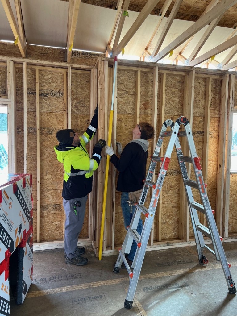
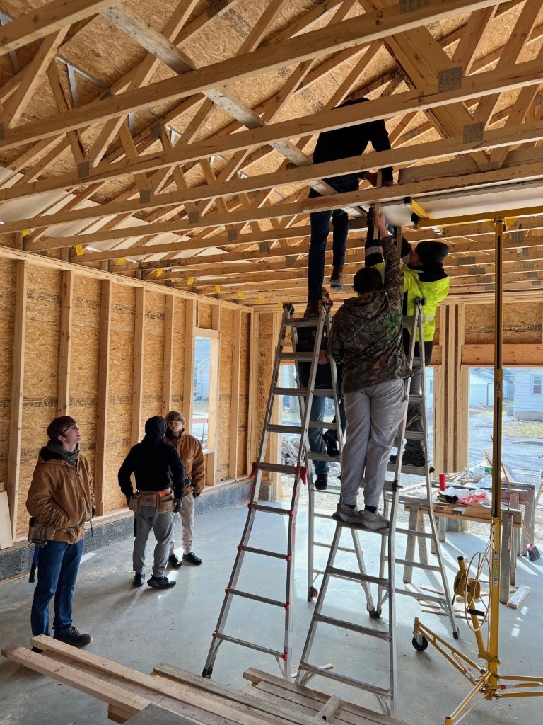
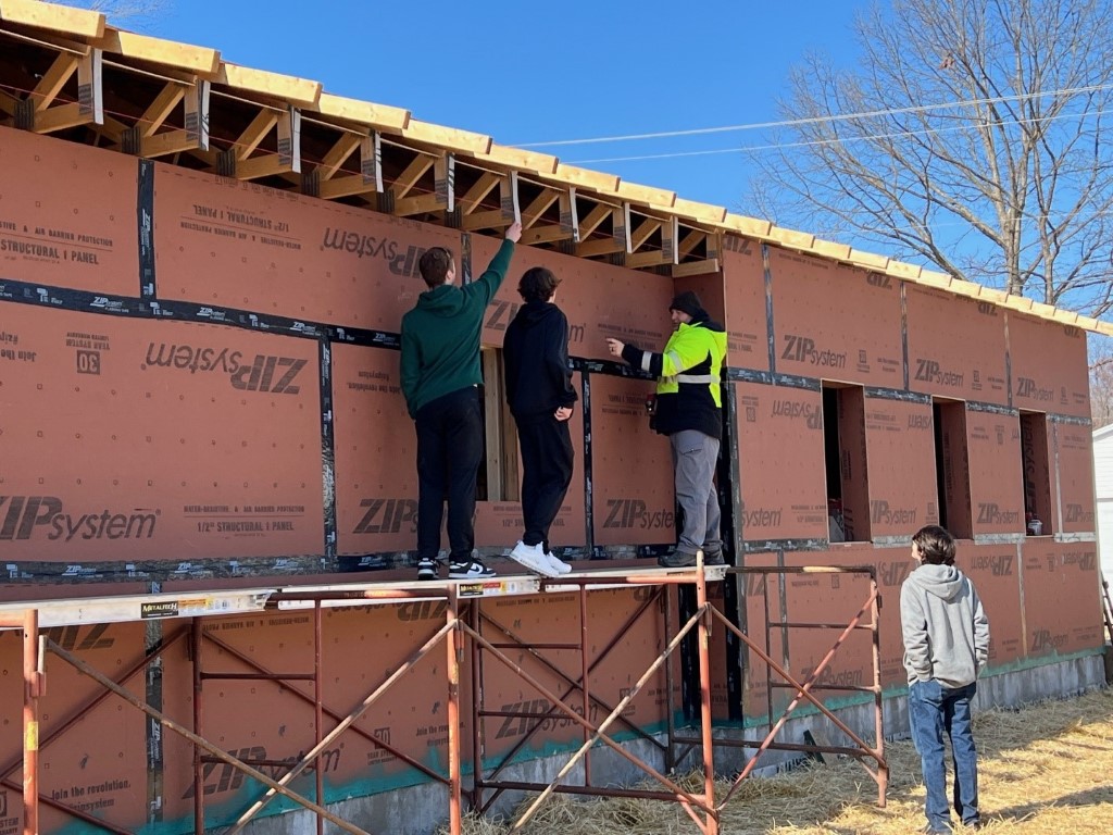
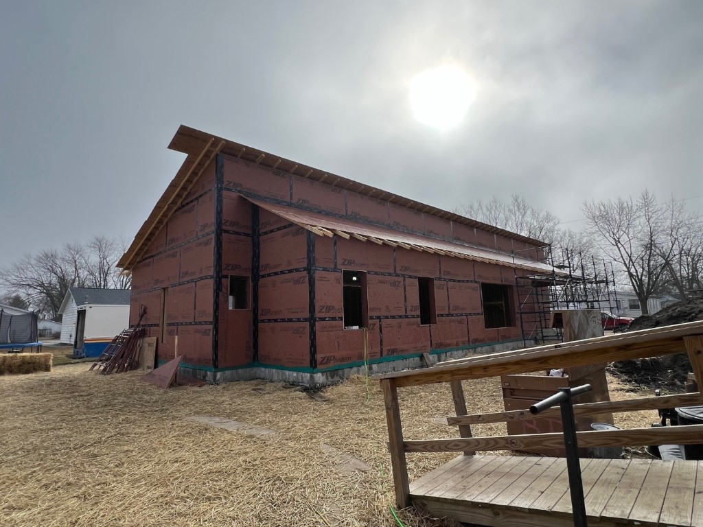
Matt Blomquist and students continue making great progress despite some bitter cold and miserably wet weather. The picture sequence below gives an idea of Matt’s recent class period activities. He has morning and afternoon student groups, plus a Monday evening class from the local community college. Matt begins each class discussing the day’s activities and objectives. The students disperse into smaller groups with Matt continually making the rounds, answering questions, and providing additional instruction. Check out Matt’s Build_Learn_Teach Instagram site to see details of their current progress.
The house is rapidly taking shape and looks great!

Economically Optimized Duct and Simplified Duct Design or, PGD (Pretty Good Duct)
Manual D is the name given to a formal computational duct design procedure. Unfortunately, Manual D does not provide an economically optimized duct design. We are going to do better than that by providing a duct design procedure that, in the spirit of the PGH movement, provides a PGD, a pretty good duct. That is, a method providing an economically optimized duct that minimizes duct installation cost and lifetime operating cost.
Duct design calculations are one of the most computationally complex analyses to perform for house design. We need to ensure that ducts are sized to deliver sufficient air to keep a room’s occupants healthy and productive, while simultaneously keeping a room’s occupants comfortable! Unfortunately, duct design is often one of those “little details” that are often taken for granted, with someone “winging” it or shooting from the hip. Once the wallcoverings go up, and insufficient flow occurs, the finger pointing begins.
In addition to ensuring that ducts are sized appropriately relative to a fan’s flow and pressure capabilities, economic optimization of duct sizing is important. Even if a fan is capable of delivering a desired flow, fan power can easily consume more power than the heat pump conditioning the air stream.
The above makes duct design seem impossible, but fortunately, it is not, and you can do it! Yes, consulting an engineer or experienced duct designer is advisable for complex systems with multiple levels of branching and fittings, but for most homes of reasonable size and number of zones, you can properly design the home’s ducting.
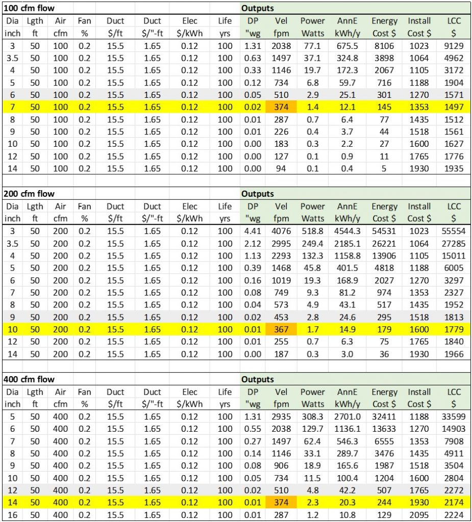
Table 1 shows duct air flow characteristics for air flows of typical interest to many of today’s high-performance homes. The table shows important flow characteristics (pressure drop, fan power, annual energy usage) and economic factors (duct installation cost, lifetime energy cost, and the sum of installation and energy cost, or lifecycle cost). The left side of the table shows input information such as duct diameter, duct length, air flow, fan efficiency, duct (house) lifetime, energy cost, and installation cost. Note that installation cost has two installation cost factors related to duct length, and a factor related to duct length and duct diameter.
Data under the shaded column headings are the spreadsheet’s output, including fan power, duct pressure drop, duct velocity, lifetime energy cost, installation cost, and lifecycle cost. For sure, duct installation cost varies quite a bit from one end of North America to another. These numbers may look low for your area, but $1600 (including materials) to install 50 feet of 10" to 12” diameter of insulated flex duct should not seem too far off for most regions. If an installer needs to cut and hack and weave and bend around several objects, perhaps a higher cost is justified.
Examining Table 1’s economic results, we see that when we add lifetime energy cost with installation cost for a “lifecycle cost”, an optimum occurs. The optimum, as in many systems, is a place where one or more factors become more dominant as another factor loses significance. In this case, as we increase duct diameter, lifetime energy cost becomes less significant than duct cost. The yellow bar in each sub-table shows the lifecycle cost optimum for 100cfm, 200cfm, and 400cfm of air flow. The optimum lifecycle cost is somewhat shallow, allowing for maybe +/-1” duct size variation without too significant of impact on energy and cost. But, notice the steep increases when one tries to reduce duct size too much. Fan power and energy cost rapidly increase as duct size decreases.
Another important characteristic to notice in Table 1 is duct velocity. Over a broad range of cost factors and air flows typical of insulated ducts for residences, an economically optimized duct system had an air velocity in the 300 to 400fpm (feet per minute) range! For more background, read our two reports on optimal duct design, and duct distribution.
Assuming 400fpm as a target for air velocity in duct design, lots of good things happen. First, your duct system will reasonably well economically optimized, that is a PGD.
Second, air flow will be quiet! Duct noise is related to the kinetic energy of air flow, which is proportional to the square of duct velocity. Yesterday’s 800 to 1000fpm rule-of-thumb for residences and offices (which often was pushed much greater than that), generates 4 or more times as much noise as a duct with 300 to 400fpm velocity.
Third, there is some squishiness with 300 to 400fpm duct velocity, allowing for times when elevated air flow is desired (eg, kitchen venting or design day comfort conditioning capacity air flow) as well as the ability to increase airflow for future additions. Note that if a future expansion is anticipated during current construction, it is best to use the future air flow for duct design analyses.
Fourth, “fitting losses” and “velocity head losses” (changes of duct cross-section area) are very small in the 300 to 400fpm range, and can be neglected.
Our duct distribution report demonstrates the difference between solving the exact duct flow and pressure drop equations to a designing a duct system by assuming 300 to 400fpm duct velocity. The difference is negligible! Ducts with 300 to 400fpm velocity are simple to balance, too, because each register controls flow unlike pressure drop restricted duct systems in which balancing is like squeezing Jello.
Table 2 brings us full circle by providing a range of duct sizes typical of residence air flows for IAQ and comfort management. One table is for round duct and one is for square duct. The table provides all the information needed for fresh air flow needs, heating needs and cooling needs within a zone. Note that heating assumes 120F delivery air and cooling assumes 50F delivery air, typical of today’s heat pumps.
These results can be extended to rectangular ducts by keeping the cross-section area the same. That is, a 6”x6” duct and a 3”x12” duct have the same cross section area with same flow capabilities as shown in Table 2. For those of you with more in-depth duct design background, the correction factors that would typically be applied because the 3”x12” duct has more perimeter are not significant for 300 to 500fpm velocities. Time is better spent in the field ensuring a quality installation with smooth duct connection and sealed joints than adding decimal points to calculations.

THS PGH Duct Sizing
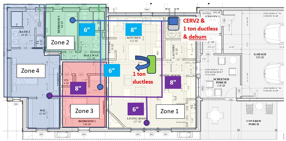
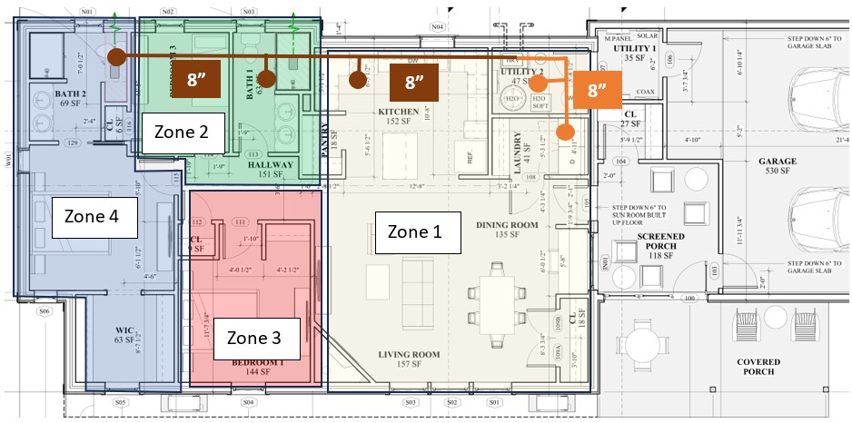
Let’s apply the preceding section methodology to the THS PGH project. From our last article, we conducted “Manual J” analyses on four house zones we defined for the THS PGH. Based on air flow requirements for air quality and for comfort conditioning, Figures 6 and 7 show supply duct and return duct systems for the THS PGH project. With the home’s insulated and conditioned crawl space, we have easy access to run ducts in any way we like, which makes duct installation efficient and reduces installation cost.
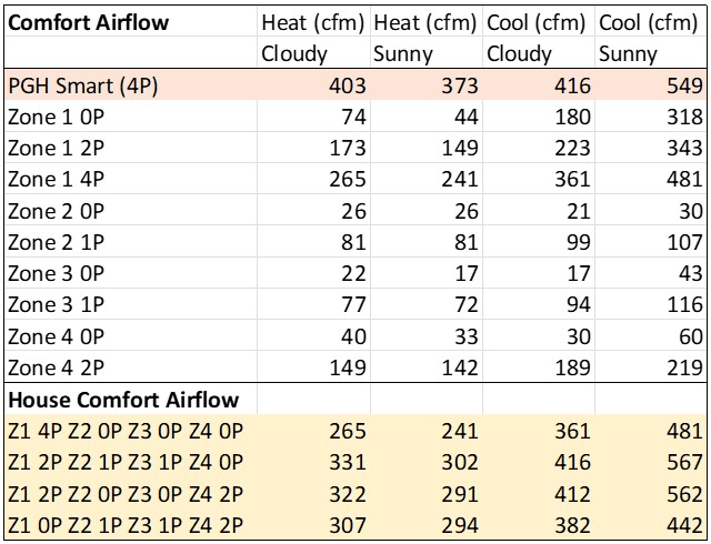
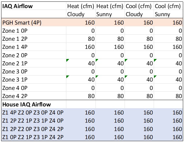
Tables 3 and 4 are from the previous THS PGH article showing air flows to each zone, with varying levels of occupants in each zone, based on air quality, heating and cooling comfort. The first row in each table (“PGH smart”) is the whole house comfort conditioning result obtained from ZEROs simulation modeling. The successive rows show Manual J modeling for each zone using ZEROs. As discussed in the previous article, our zone modeling includes the movement of home residents into each room, along with their individual needs for air quality and comfort in those zones.
Cooling dominates air flow needs in the home, with approximately 560cfm of total air flow. Zone 1, the open living area requires 480cfm on a sunny design day with 4 occupants. For air quality, zone 1 requires 160cfm of fresh air flow based on Build Equinox’s healthy IAQ Standard, which is twice the air flow required today’s odor-based, inadequate ASHRAE 62.2 ventilation standard.
The master bedroom (Zone 4) may require as much as 220cfm on a sunny, design day cooling day when occupied by 2 people, with 80cfm required for maintaining excellent indoor air quality, and 150cfm required for design day heating on a cloudy day. The other two-bedroom zones, assumed with single occupancy, require less than 100cfm each on design day heating and cooling day extremes, and otherwise less air flow for comfort.
We note that fresh air needs vary with human metabolism. For sedentary activity (typical movement around a house), 40cfm of fresh air per person will keep the indoor environment at 800ppm of CO2. During sleep, metabolism is lowered, with fresh air needs dropping to 20 to 30cfm per person for maintaining 800ppm of CO2. Periods of exercise and physical exertion (cleaning, cooking) elevate fresh air needs by 2 or 3 times (80 to 120cfm per person). The CERV2 automatically detects these fresh air requirements as activities and occupancy vary, and adjusts fresh air ventilation accordingly.
Most of the time (more than 99% of the time), design day conditions are not occurring, reducing comfort ventilation needs. Fresh air needs, however, continue such that on a day with very little heating or cooling, the CERV2 continues to modulate fresh air as dictated by CO2 and VOC levels.
Based on the above considerations, Zone 2 and 3 can be supplied with 6” round or square ducts, providing 80 (round) to 100 (square) cfm of air flow with our recommended 400fpm to each bedroom zone. Note that there is enough “squishiness” for the CERV2 and ducted minisplit to move higher airflow to these rooms during extreme weather. There is no problem with using larger 8” ducts branches to these bedrooms.
The main living area (Zone 1) can use a 6-inch duct branch for 80 to 100cfm supply air, while the master bedroom (Zone 4) is shown with an 8” duct branch to meet design day comfort needs up to 220cfm. These duct branches are plenty large for supplying fresh air needs above and beyond assumed occupancies.
Note that Zone 1 requires nearly 500cfm during extreme weather when fully occupied. We will discuss the comfort conditioning system design in the next article, but for the present, note that a 1-ton ductless minisplit heat pump located in the main living area supplies up to 400cfm of comfort conditioning air flow, which when combined with air flow delivered by the CERV2/ducted minisplit unit, satisfies extreme weather comfort air flow. There are some other advantages to the ductless and ducted heat pump arrangement that we will discuss in the next article.
Two 8” supply duct trunks from the CERV2/ducted minisplit connecting zone duct branches are shown in Figure 6. During typical conditions, the CERV2 will be operating at 200cfm air flow with 100cfm directed to each trunk. As comfort conditioning capacity increases, the CERV2 automatically increases air flow to 400+cfm (200+cfm per trunk).
The CERV2 contributes the first line of comfort conditioning. As temperature deviates from a desired temperature setpoint, the CERV2 senses the increased comfort capacity need and initiates “Stage 1” heating or cooling (roughly 50% of the minisplit capacity, however, there are capacity modulations occurring within each Stage setting). If additional capacity is required, the CERV2 detects the additional need, adjusting fan speeds and moving to Stage 2 capacity.
Return ducts follow a similar strategy as the supply ducts. We recommend placing returns in all bathrooms (but not supplies), kitchens, laundry, and other moisture, odor, or non-occupied rooms (eg, crawl space, walk-in closets). By continuously drawing air into bathrooms, bathrooms dry out. Note that bathroom air should be as fresh as the air everywhere else in a home, and in CERV2 homes, it is.
Some air should flow through all spaces in a home whether or not occupied. For non-occupied spaces, air flow is generally a nominal amount (eg, a 2” or 3” duct opening) that keeps air fresh and avoids moisture buildup.
We show 6” branches from the two bathrooms and the kitchen connected to an 8” trunk returning to the CERV2 unit. Approximately half of the return airflow (100cfm) will follow this path during normal CERV2 ventilation and recirculation modes. The remaining 100cfm of return air to the CERV2 moves through the main living area to the laundry and mechanical room. Note that when bedrooms are unoccupied, fresh delivered to those rooms is delivered to occupants in the main living area. The CERV2’s whole house recirculation and filtration mode also ensures that all fresh air delivered to a home is efficiently used to benefit home occupants wherever they are located.
A heat pump water heater will be located in the mechanical room with the CERV2 unit, too. Return air into the mechanical room maintains room temperature conditions in the mechanical room, maintaining heat pump water heater efficiency and capacity at all times. We will discuss this aspect of system design in an upcoming article.
Next Time
Maintaining good air quality is more than simply blowing some air at a specified ventilation level into house and assuming air quality is good. Effective distribution is essential to ensure stale air is purged from a home.
THS PGH will have excellent air quality and will be very comfortable in all weather conditions. Follow our next article on IAQ and comfort conditioning system design to learn why!
