Key Points:
• This is a continuation of our “New Lungs for a 101-Year-Old Home” project, where a CERV2 Smart Ventilation System was integrated into an existing central furnace/AC system. The existing supply ducts for the kitchen and bathroom were converted to return/exhaust ducts for the CERV, and a new exhaust duct was added for the previously unducted half-bath. Zone dampers were also installed for smart spot-ventilation.
• In Part 2, we took a big leap and removed the entire central furnace/AC, and replaced them with two new ultra-efficient 1-ton ducted Mitsubishi Hyper-Heat mini-splits. This involved re-ducting the whole house too!
• Mitsubishi Heat Pump Model Numbers - Indoor Units: PEAD-A12-42AA7, Outdoor Units: SUZ-KA12NAHZ
• Many thanks to Mitsubishi for sponsoring this project with the donation of the heat pumps! Mitsubishi has worked hard to stay at the forefront of energy efficient comfort conditioning, and their new products really open up new pathways for heat pumps in the toughest climates. Illinois has hot, muggy summers, and dark, bitter cold winters, so stay tuned for performance and efficiency data in an upcoming article!
• Ductwork is challenging and takes a great deal of planning to get right. I have great appreciation for all you HVAC technicians out there!
CERV Retrofit - New Lungs for a 101-Year-Old Home
Written by Alex Long, co-founder of Build Equinox
Welcome back for round two! We took a bit of a breather after part 1 (integrating the CERV2 into our existing furnace/AC), but now we’re back at it! Our end goal of this project is to demonstrate how to completely retrofit an old home’s HVAC by removing and replacing the old inefficient 100 kBTU gas furnace, 3-Ton AC, and gas water heater. The furnace and AC will be replaced by two new ultra-efficient 1-ton ducted Mitsubishi Hyper-Heat mini-splits and the gas water heater will be replaced with a Rheem hybrid-electric water heater (stay tuned for part 3). And most importantly, the CERV provides fresh air to the home when things get stinky!
Why go through all this trouble? Because we can...and should! By removing the natural gas appliances in our home we will:
• Lower our utility bills. Service fees for natural gas keep climbing, and alone add up to nearly $400 every year! Winter heating can be efficiently accomplished with electric heat pumps. The Mitsubishi H2i Hyper-Heat units still retain full capacity down to 23F, and even at -13F only drop to 76%.
• Improve air quality. If you have gas combustion inside your house, you don’t have good air. Approximately 50,000 people in the U.S. visit the emergency department each year due to accidental CO poisoning.
• Decrease infiltration. Since we didn’t have an “external combustion air” furnace, the furnace and water heater used inside air for combustion. That air is blown out through the flue chimney, which puts a negative pressure on the house and sucks unconditioned outside air in through gaps and cracks.
• Not explode. A few weeks ago I saw a huge plume of black smoke as I drove to work, where a house literally exploded from a natural gas leak. From the article: “A patron of the nearby Cracker Barrel restaurant on Kenyon Road said that her family saw the ‘whole roof fly straight up over the treetops’”. Luckily, no one was seriously injured, but I prefer my roof to still be attached to the walls.
Pre-Retrofit Layout
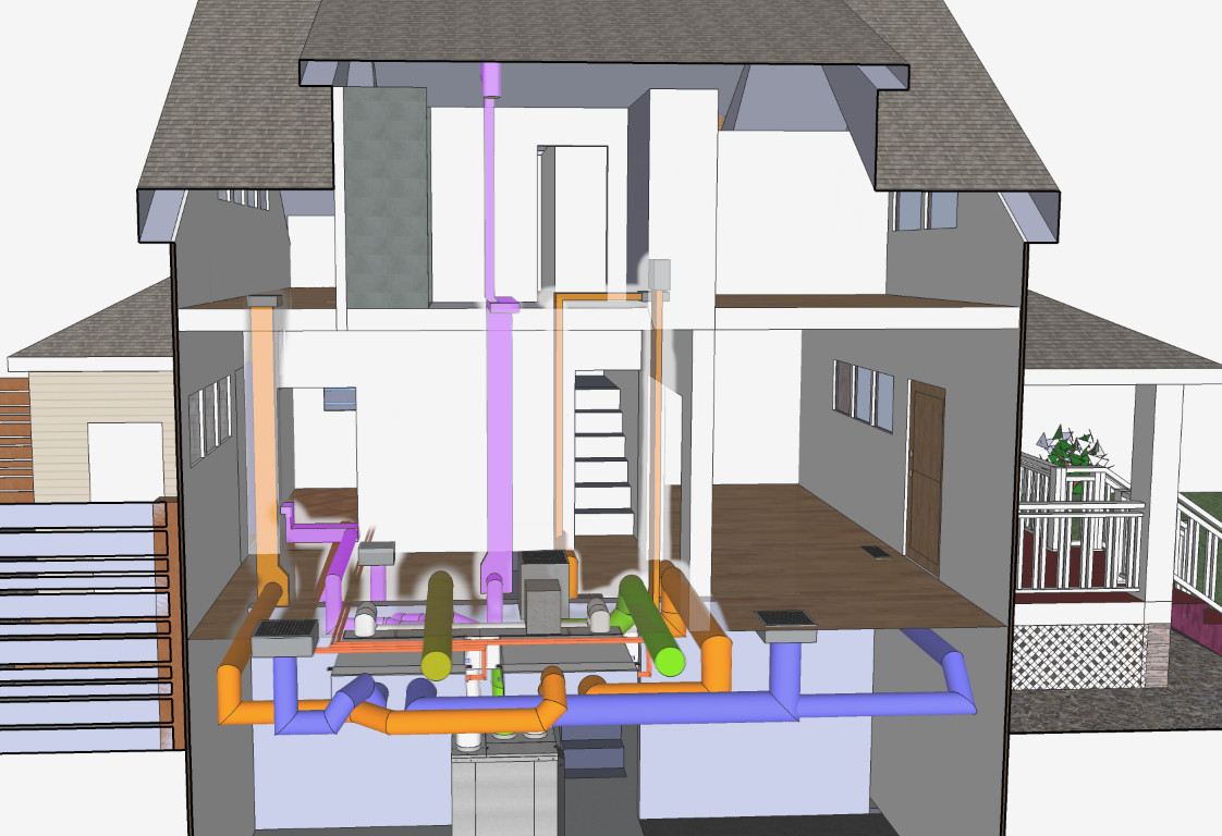
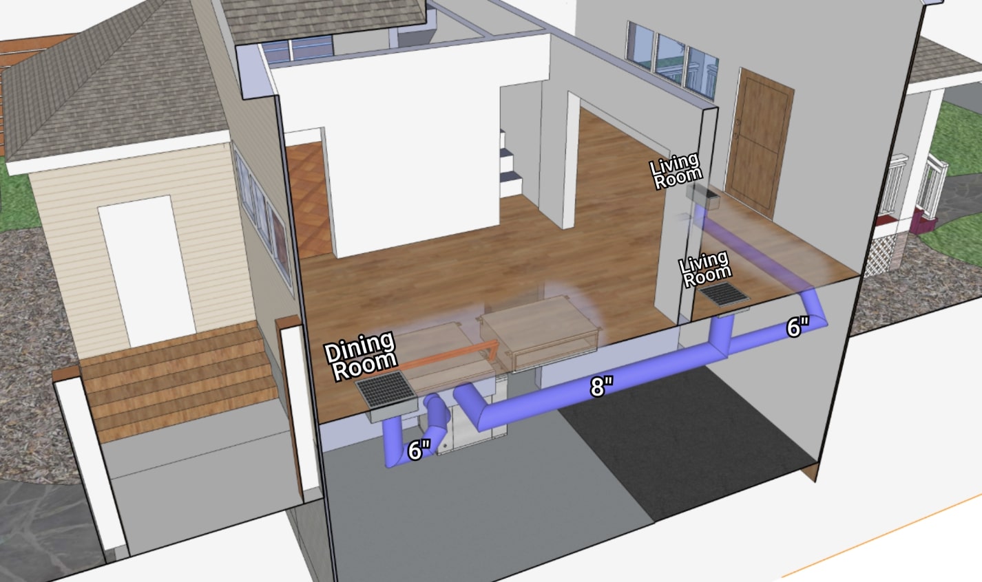
Lets take a quick look at how the home was ducted (this was mostly covered in the Part 1 Article). The returns for the 1st floor half bath and kitchen, as well as the 2nd floor full bath, are all connected directly to the CERV so that it can quickly exhaust these spaces when pollutants are high. The 1st floor dining room return is directly connected to the central furnace. The CERV outlet is also ducted to the furnace inlet, allowing it to feed fresh air into the supply ductwork for both floors. This is a good airflow layout, and will stay the same, but the manner in which we accomplish it will change!
Removing the old furnace and AC
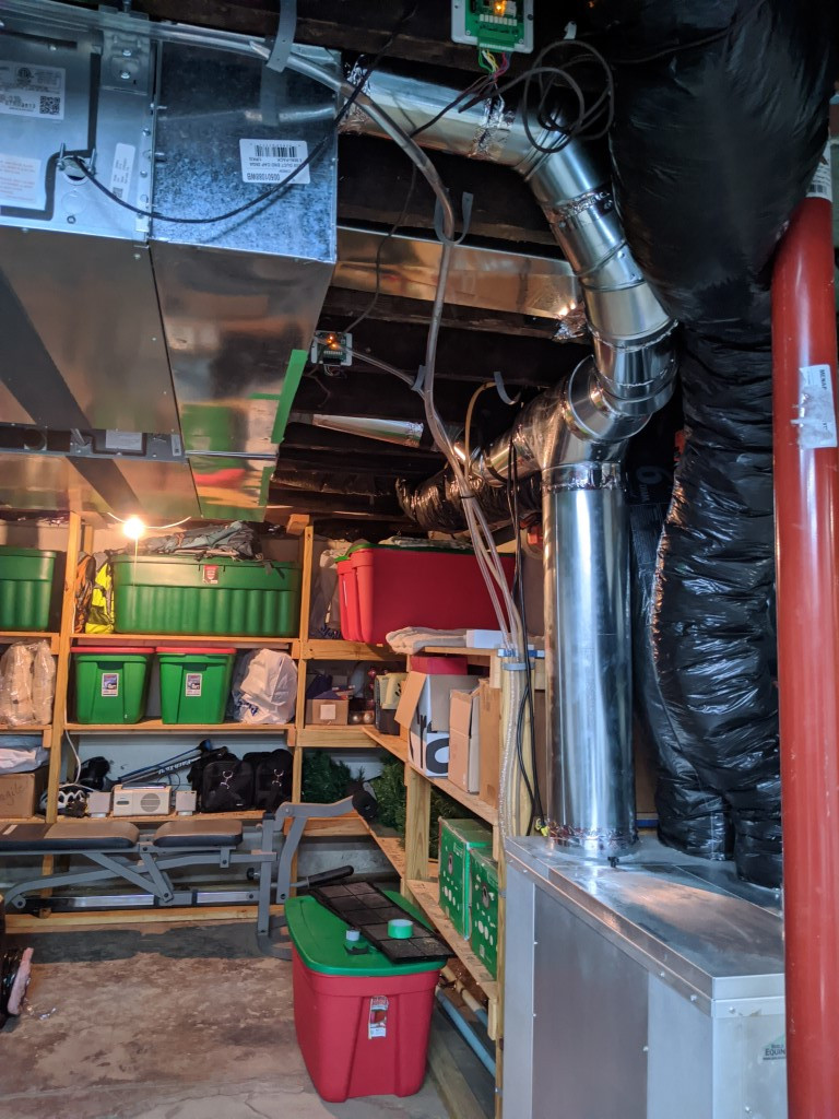
 Behold, the monstrosity. This isn’t actually a load-bearing wall, but at some point in time I’m sure this wall was used to hold up some ugly wood paneling.
 I added in an extra support column to an area where the joists had been cut for the return register to the furnace. Don’t let the aluminum tape fool you, most of the ductwork was being held together by crumbling ancient duct-tape (alternatively, they very well may have been mummy bandages).
 If you’re taking out an old air conditioning system, ALL of the refrigerant must be captured. It’s bad for the environment and the fine for releasing refrigerant into the air is many thousands of dollars.
The furnace and AC were fully removed, as well as the ductwork to each register. All the ducts were filthy, but I scrubbed them down to reuse for the new system. The furnace and AC unit were still in good condition, so I sold them online.
Installing the outdoor unit
Now that all the old stuff was removed we can put in the new stuff! We started with installing the outdoor units.
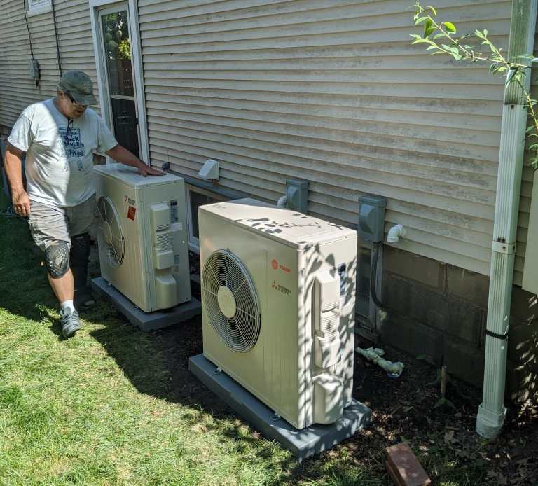
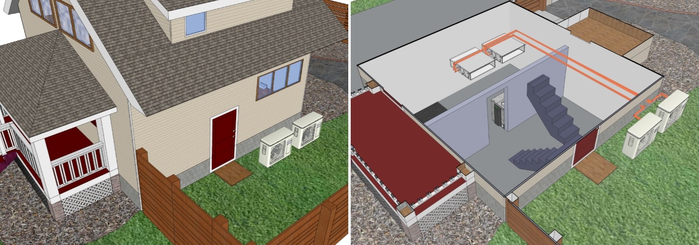 The two outdoor units are going in roughly the same location as the old AC’s outdoor condenser, on the North side of the house.
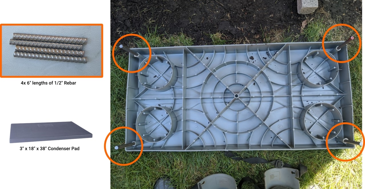
 The outdoor units need to be raised off the ground to protect against snow and ice buildup during the winter. We’re using Diversitech EL1838-3 condenser pads, which measure 3” x 18” x 38”. To help protect the pads from moving laterally, we inserted 6” lengths of 1/2" rebar in each of the corners of the pad (the rebar will stick into the ground once we bolt down the units).
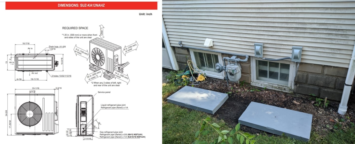 Left: Dimensions and required clearances for the Mitsubishi SUZ-KA12NAHZ 1-ton outdoor unit.
 Right: Pad locations for the two outdoor units, properly spaced. Two outdoor disconnect boxes (Part: Eaton DPB222RP) were installed, each with a 15A 2-pole breaker.
The main power coming into the unit is 208/230VAC (14 GA wire in the far right 2 terminals). The outdoor unit actually powers the indoor unit, so the 3 terminals on the left labeled S1, S2, and S3 are connected with 14 GA 3 conductor + ground NM-B cable. S1 and S2 are the main power terminals for the indoor unit (208/230VAC again), while S3 is the communication line so the indoor and outdoor can talk.
Hanging the indoor units
Next step was installing the indoor units in the basement near where the old furnace/AC was. From rough measurements, it looked like we would need approximately 40 feet of refrigerant tubing and wiring between each indoor unit and outdoor unit. The outdoor units come pre-charged with refrigerant, and luckily 40 feet is short enough that no extra refrigerant would be needed.
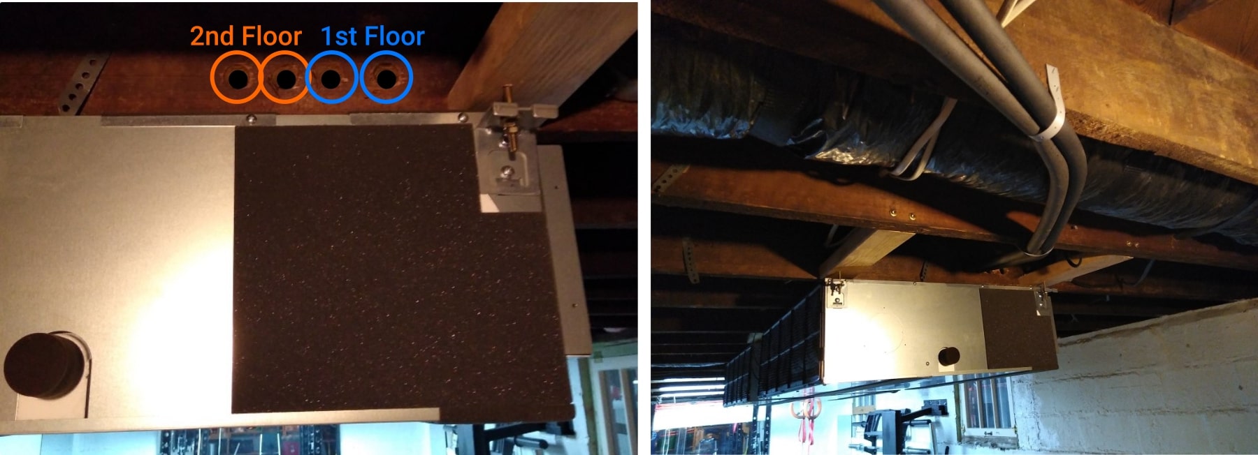
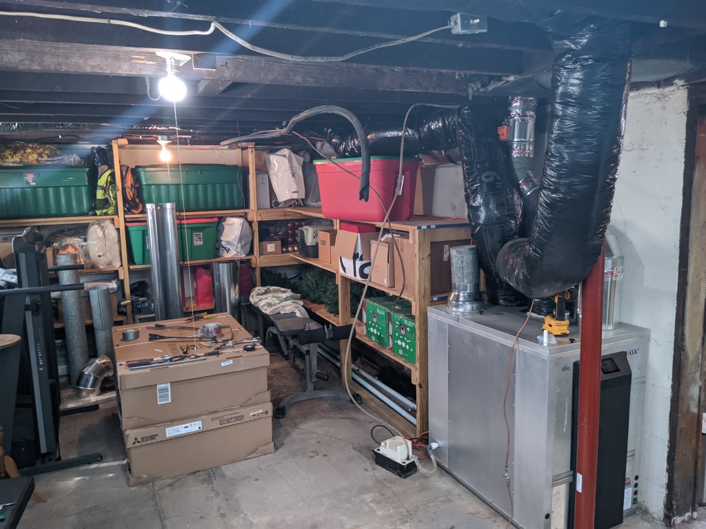 The two indoor units boxed, but ready to hang. They’re light enough that they can easily be hung from the floor joists.
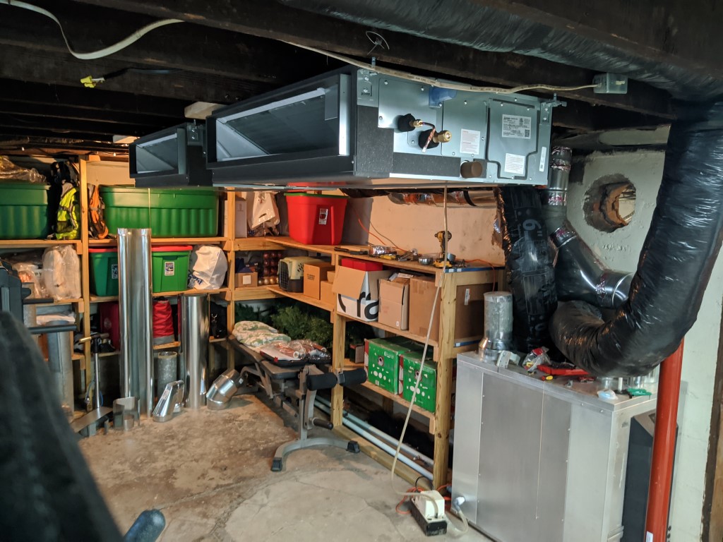 Ta-Da! The main concern when hanging the indoor unit is keeping everything level so that condensate can properly drain.
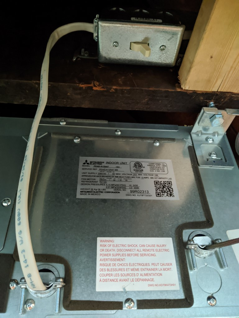
 For wiring the indoor unit, it’s required to have a disconnect switch to easily shut off power. I used a 30A 120/277 VAC Double Pole light switch (Part #: PS30AC2ICC6) connected to lines S1 and S2 before they enter the indoor unit.
For the refrigerant piping, the cleanest installation required drilling four 1” holes in the joists above the hanging indoor units. Each system has two refrigerant lines – 1/4” copper tubing for liquid refrigerant, and 3/8” for vapor refrigerant. The copper pipe is then insulated with flexible rubber foam pipe insulation (McMaster Part #s: 4463K23 for 1/4", and 4463K121 for 3/8”).
Refrigerant connections on these units are all “Flare” style fittings. This is an area that you want to be very very careful and neat! A bad flare fitting can cause your system to leak out its refrigerant and potentially cause damage to the system.
Time to check for leaks! The refrigerant is still all sealed in the outdoor units, so we want to be sure the new refrigerant pipes are leak-free before we let it out. This involves first pressurizing the piping with Nitrogen, then using a soapy water solution to see if we get any bubbles at any of the flare fitting joints.
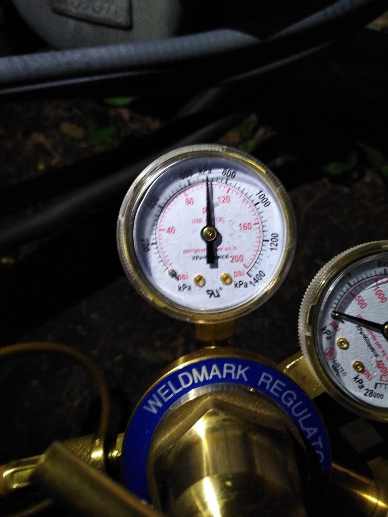
I pressurized the piping in both systems to 100psi, and no leaks were found! Just to be extra sure (my wife often calls me “extra”, I wonder if this is what she means...), I left the pipe pressurized over night and checked to make sure we still had 100psi.
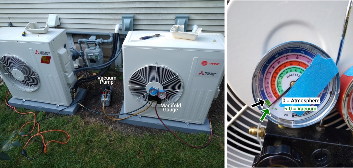
After pressurizing with Nitrogen the next step is to pull a vacuum on the refrigerant pipes. This is very important because air left in the pipes will contain moisture, and that moisture will react with the refrigerant to do nasty things to your brand-new heat pump. I ran the vacuum pump while eating breakfast, then left it to sit again for another day to make sure they both still held vacuum. Because I’m extra.
That’s about it for the indoor and outdoor unit installations! All in all, I estimate it took my dad and me about 3 full workdays, with plenty of trips to the hardware store mixed in. All the assorted parts (refrigerant pipe, fittings, insulation, mounting pads, etc.) added up to about $400. Next up – ducting!
Ducting: Theory
You may be asking yourself: why two 1-ton units instead of one 2-ton? Installed cost would definitely be lower, and there’d be half as much work to do.
Well, here’s a big ol’ report we wrote 2 years ago, if you feel like a good read. For a short answer, though, I want to be able to zone the comfort conditioning in my house between the first and second floors! I expect to see even lower utility bills, but we’ll get to that in an upcoming article about performance.
To make things nice and easy, each floor only has 3 supply registers. The first floor has one in the dining room and two in the living room. I created a custom outlet plenum for each minisplit with one 6” round duct outlet and one 8” round duct outlet (design shown a in the next section). For the first floor, the 6” duct outlet will travel directly to the dining room register. The 8” duct will actually carry air to both of the living room registers – once it reaches the first, it has a Tee connection and then reduces the duct size to 6” for the other living room register.
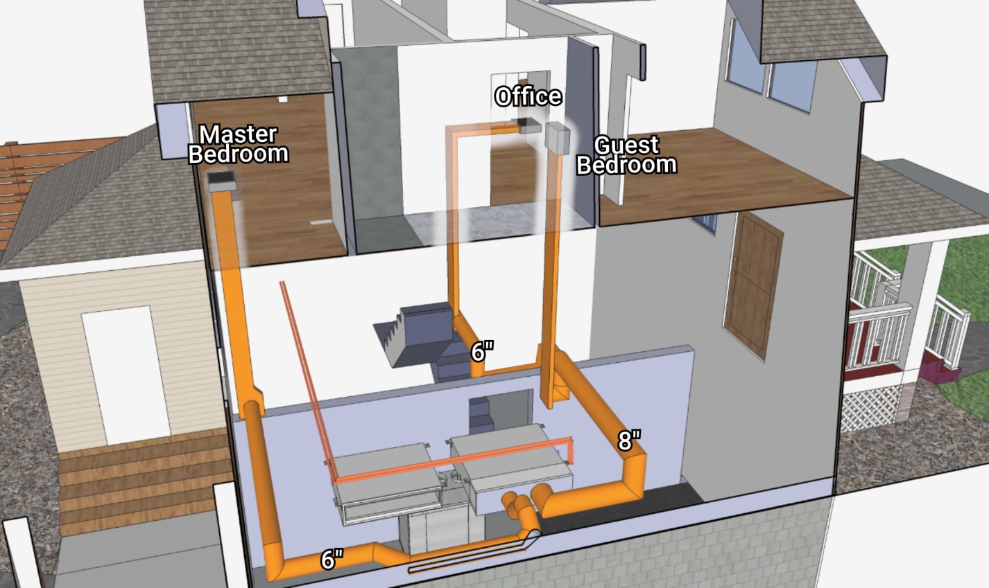
Similarly, the second floor repeats the same pattern. The duct to the master bedroom is 6” diameter, while an 8” duct brings air to the guest bedroom, then tees and reduces down to 6” for the office. The vertical duct stacks in the walls up to the second-floor measure approximately 3” x 12”, which is roughly equivalent to 7” round duct in terms of pressure loss.
Ducting: outlet plenums
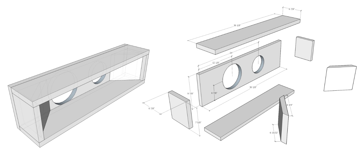
As mentioned earlier, here are the heat pump outlet duct plenums, along with the part dimensions. This was made out of a duct-board called “Koolduct”, which is not only structural, but also R8.0 for a 1 3/16” panel! We use this high-quality duct-board in the CERV, so I was able to apply my employee 5-finger discount for some scraps.
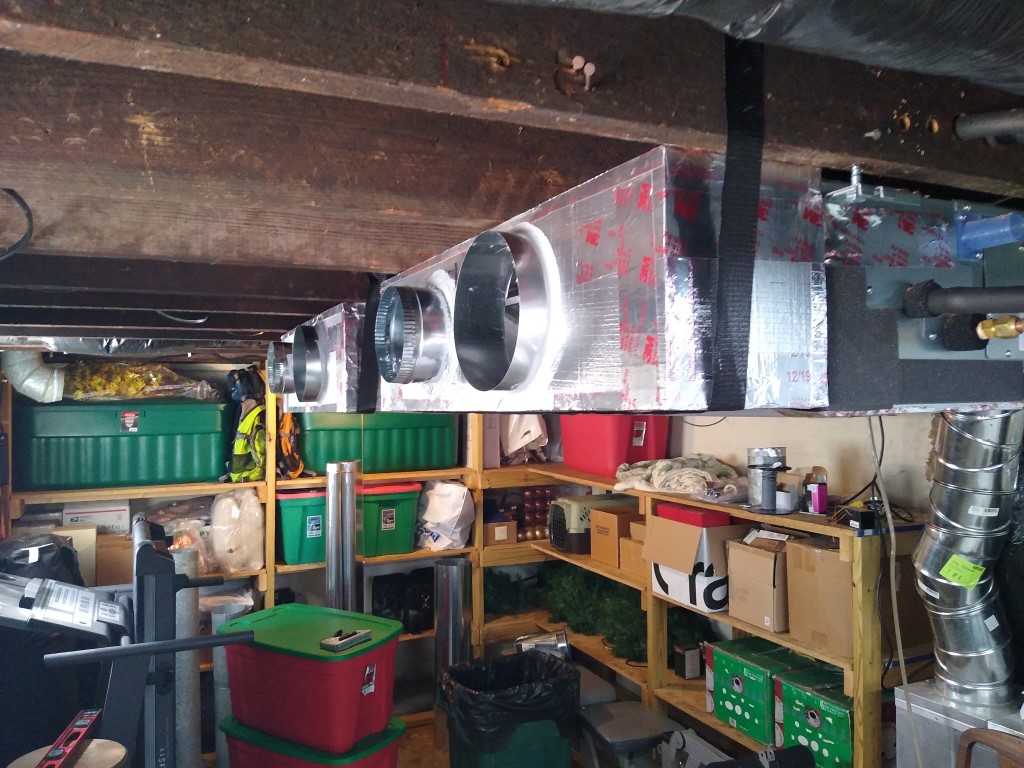
I added foam gaskets on the back side of the plenums to help seal against the heat pumps, then secured to the units with aluminum tape and used duct strap to add vertical support.
Ducting: Ducting the Ducts
A 95 degree heat wave was rapidly approaching, and we needed cooling ASAP! I reused all of the old ductwork we had removed (after cleaning of course), which saved a ton of money. Ductwork was hung with “Duct Support Webbing” (part # PS134B-4RL), and duct joints were screwed together with sheet metal screws and then painted with mastic to seal. Might as well do it right this time around!
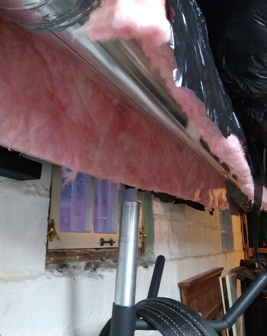
Proper ductwork installation also includes insulating the ductwork! Even though all the ductwork is within conditioned space in the basement, we still want to minimize losses before the air gets to its destination. To insulate the sheet metal ducting, I used the fiberglass insulation sleeves from flexible insulated ductwork. In some cases, I was able to slide the sleeves right over the ductwork, but other times I had to cut the outer plastic sleeve, then wrap the fiberglass and re-tape the seam.
The insulation’s black sleeve also helps make the ductwork a little less noticeable and organized. Not looking too bad!
Ducting: CERV outlet & Central inlet
So now the heat pumps can deliver comfort conditioning to the rooms. The CERV can pull stale air from the bathrooms and kitchens. How do we connect the CERV to the heat pumps?
The general rule of thumb for comfort conditioning is: 400 CFM (cubic feet of air per minute) per ton of air conditioning. Now, the CERV’s airflow capacity is pretty close to that, so if we only had one ton of conditioning, we could directly connect the outlet of the CERV to the inlet of the heat pump.
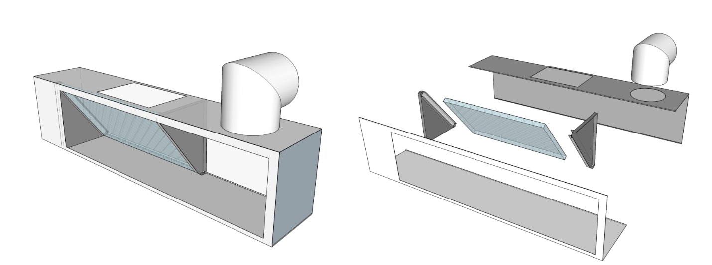
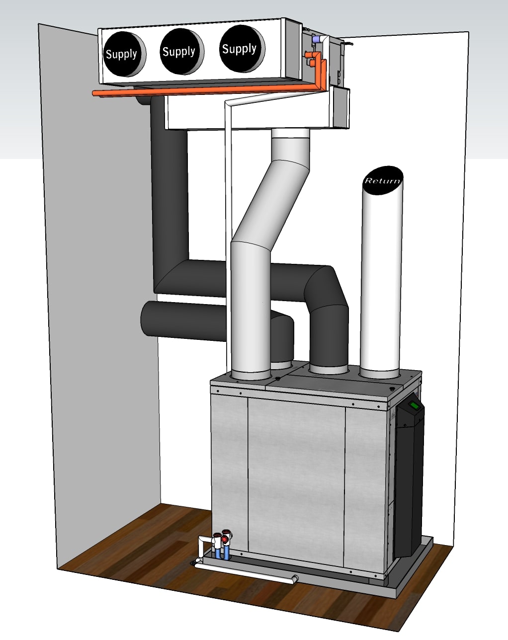 If only it was this easy and we had one heat pump. Click the image above to check out our Sketchup model for ideas how to interconnect the CERV to a single unit.
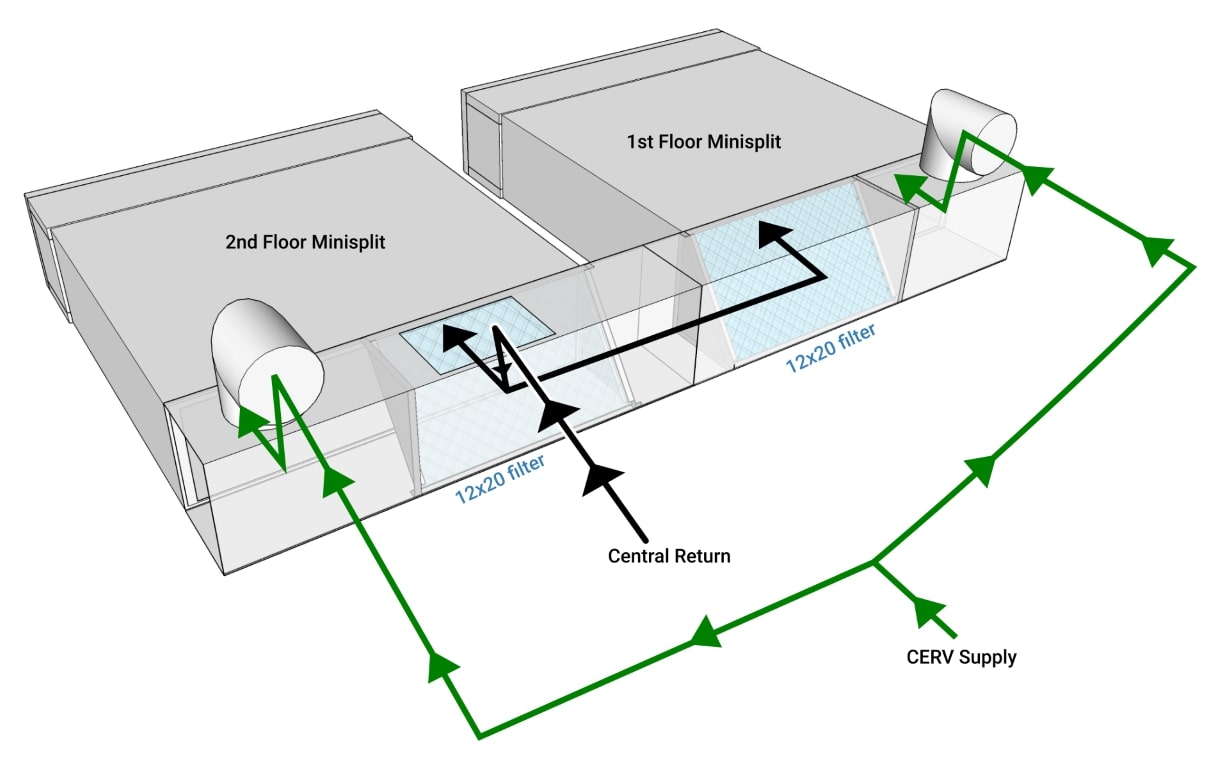
But we have two. 800 CFM would be way too much airflow to go through the CERV, so we need a different solution. We need the heat pumps to have their own central filtered intake, but we also need the CERV to be able to inject its fresh air supply to the heat pumps.
Hopefully this will help with any confusion, because it took me forever to conceptualize and design. The CERV’s supply air is already filtered, so we don’t want to pass it through another filter and slow it down. But if we have another parallel central return to the heat-pumps, we definitely want that air to be filtered because our house is a cat hair factory.
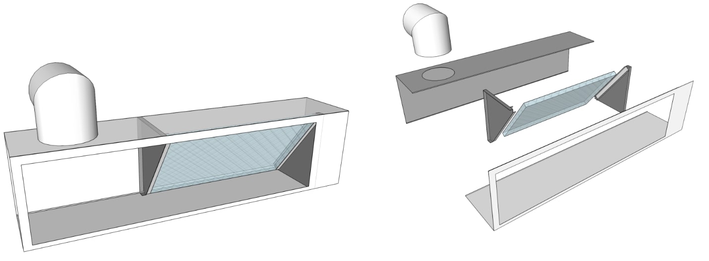
The common return plenum for each of the two heat-pumps is made with 8” x 10” rectangular 28ga sheet metal duct. The above designs were cut from the sheet metal, then fastened together, as seen below.
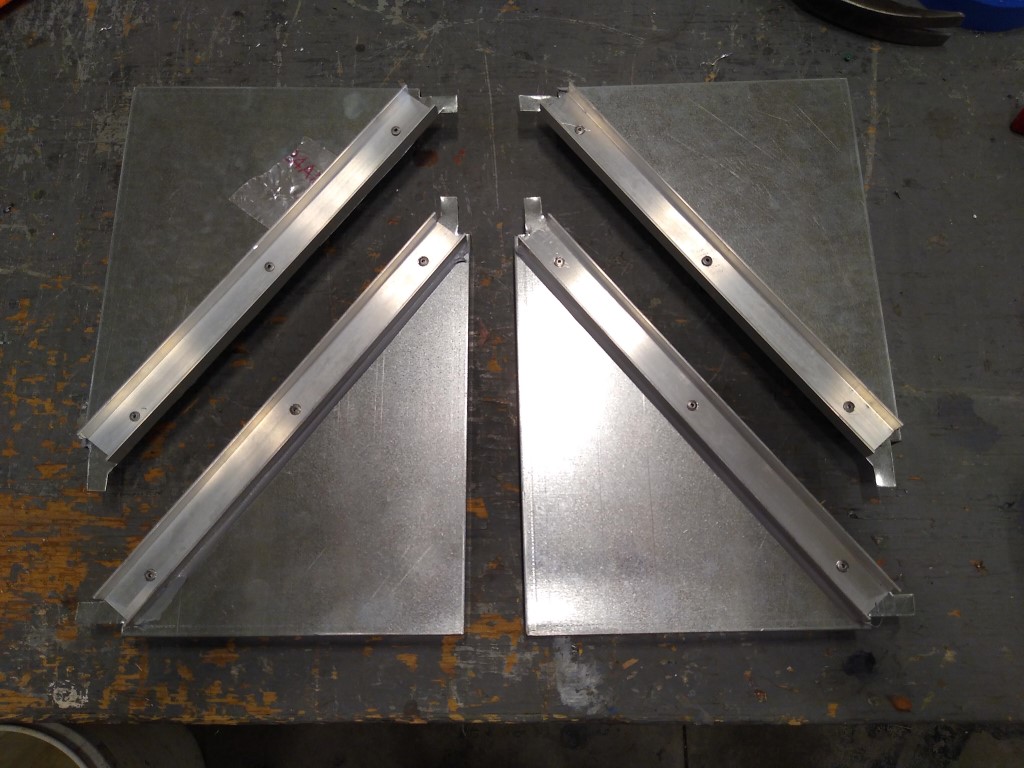 12” x 24” filter brackets. The filter slides up into the return plenum with the help of 1” C Channel.
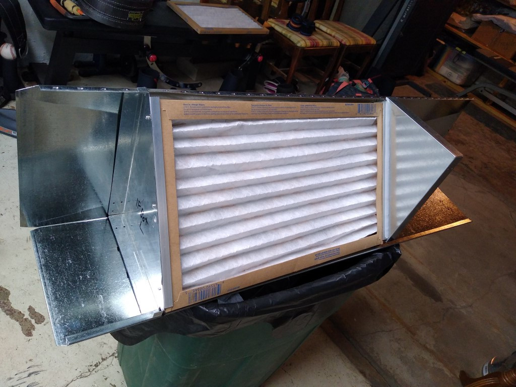 Filter brackets mounted into one half of the 8” x 10” rectangular duct (this is for the 1st floor unit).
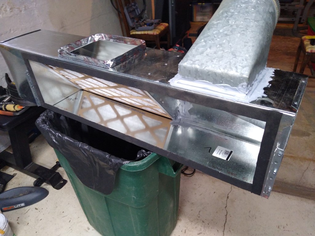 Assembled return plenum for the 2nd floor unit. The square opening will be the central return, and the duct fitting will attach to the CERV. Foam gasket is used around the large opening that mates to the inlet of the heat-pump.
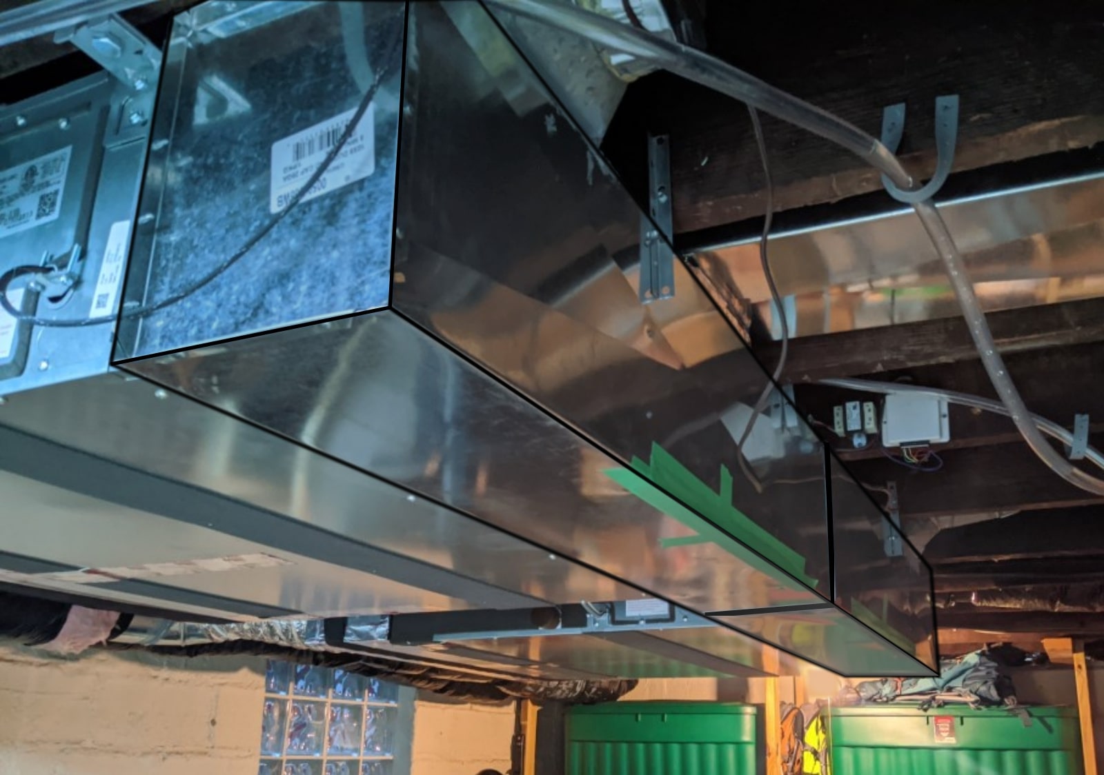 Return plenums mounted. Apologies if this makes your brain hurt, the duct is just so shiny that it was hard to get a good picture.
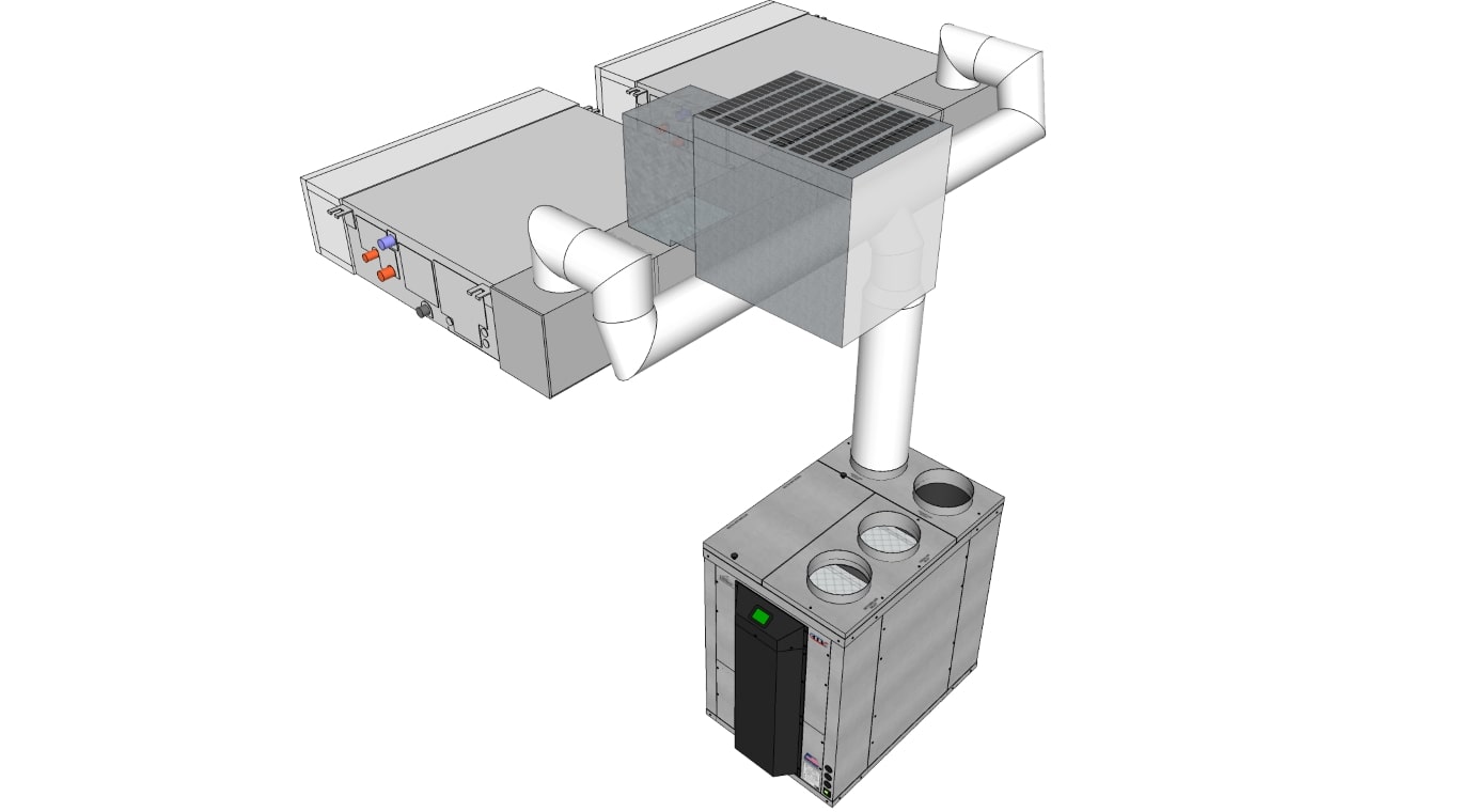 Here’s conceptually how it looks with ducts connected. The outlet of the CERV is 8” round, which then tees off to two 6” ducts – one to each mini-split.
The green tape at the bottom corner of the return plenums is where the filters are inserted. I’m going to make a nice little latch that opens for an easy filter change.
The End Result
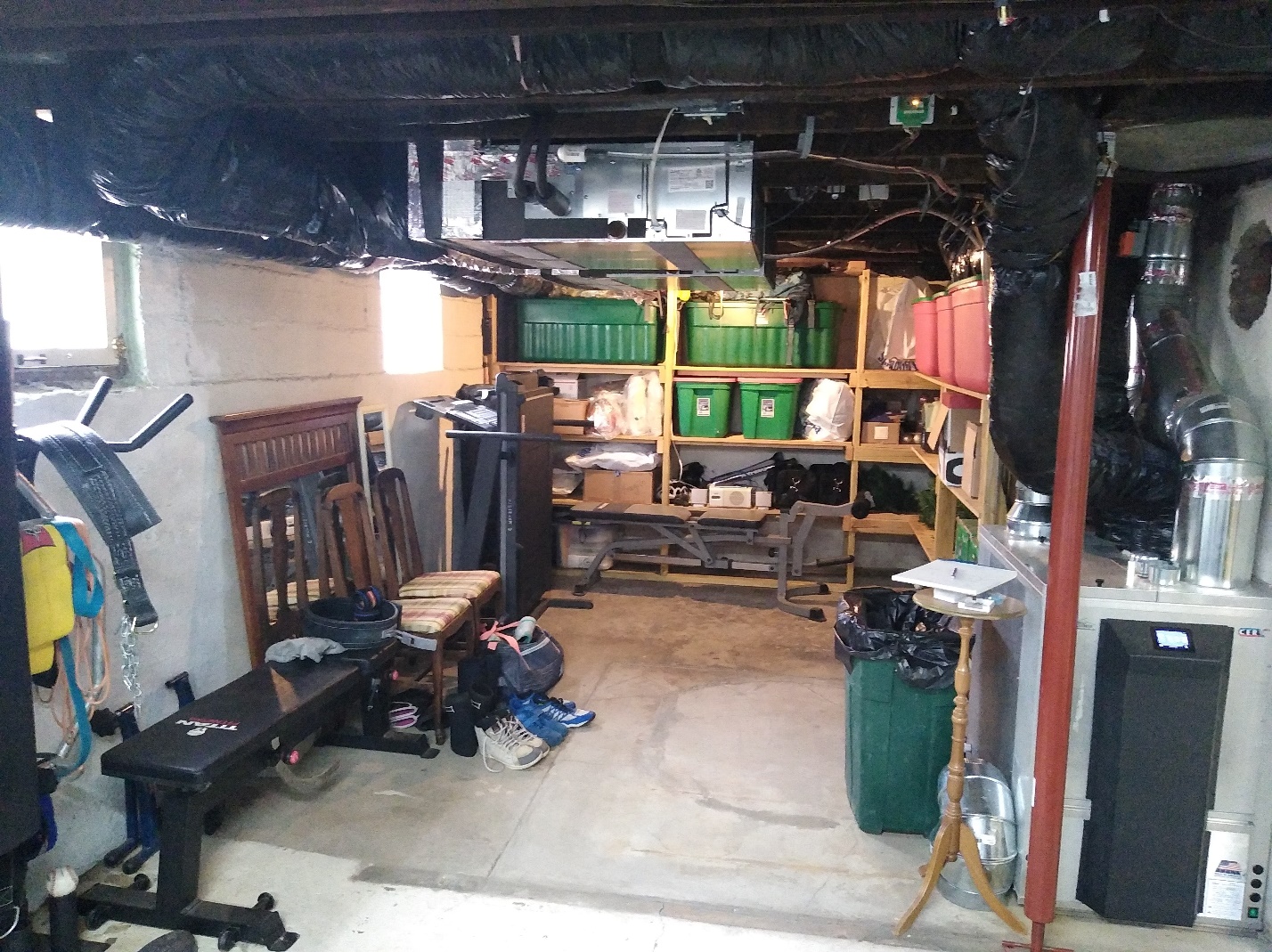
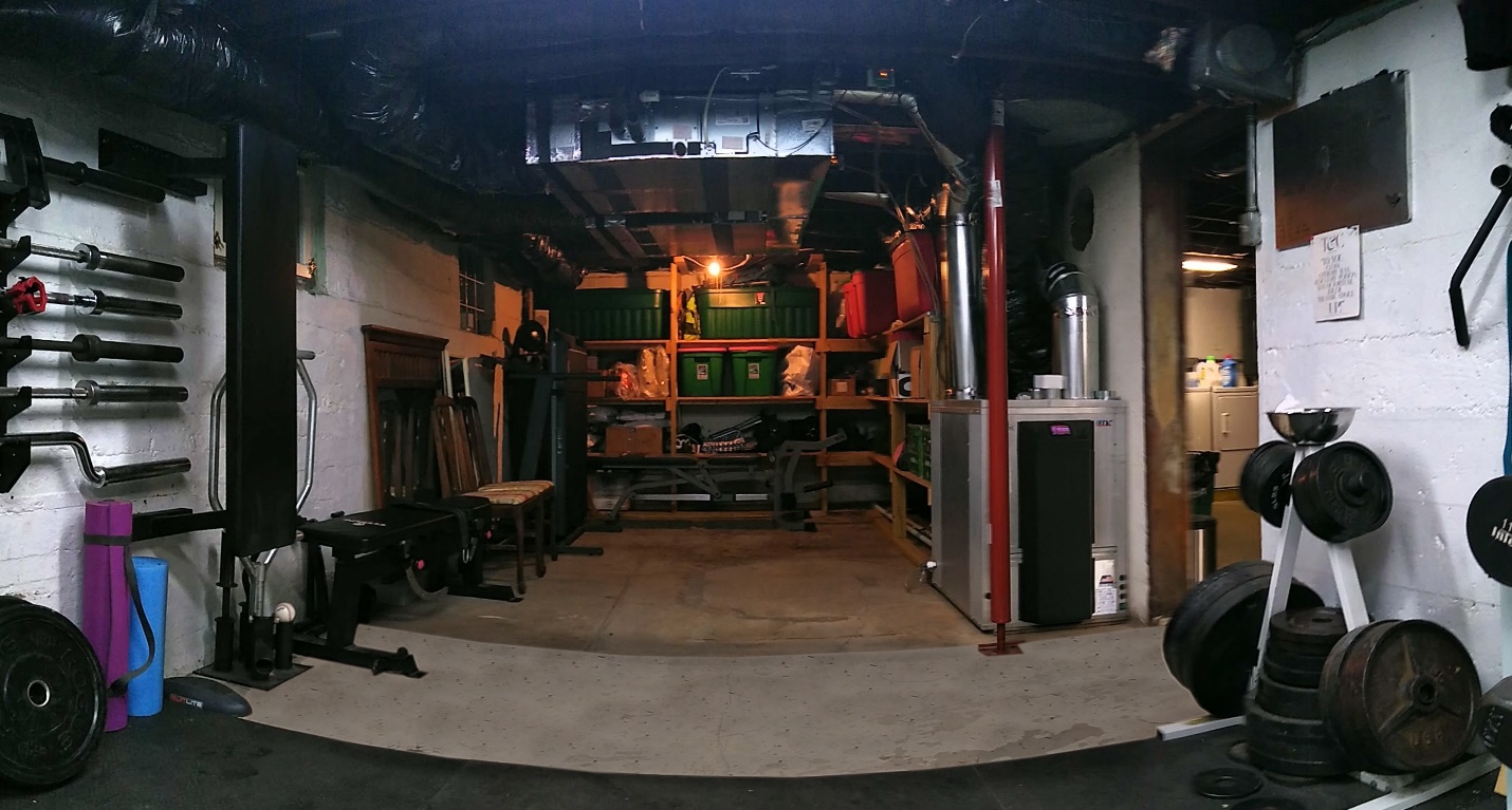
I have fooled you all, because the whole reason for this project was to make our gym space larger! Seriously, though, this project has basically opened up an entirely new room’s worth of usable space, and that’s very valuable! The average cost per square foot for a home in the US is $123 (source: Realtor.com), so you might as well put it to good use. I’ll be extending out our rubber gym flooring back into this previously unused space.
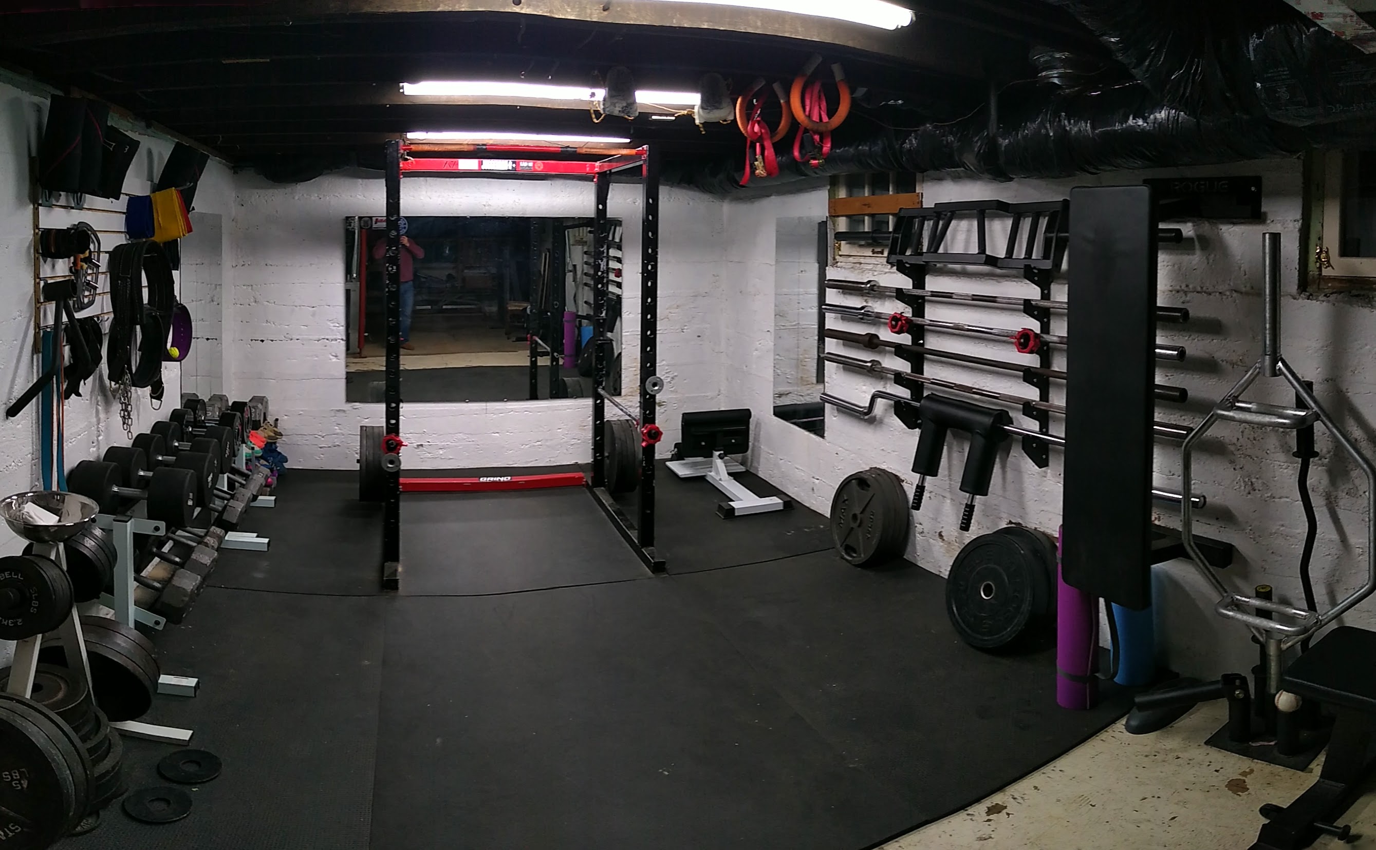
And while I’ve got you here, I’m going to brag about our home gym setup
We have:
• A Rogue Ohio Power Bar, York Power Bar, 2 beater bars, Football Bench Bar, Safety Squat Bar, Trap Deadlift Bar, EZ Curl Bar
• Dumbbells from 15lbs up to 110lbs
• 1300 lbs of barbell plates
• A custom metal Power Rack, designed and poorly welded by yours truly
Now think about how much more we can fit with the extra space!
New Lungs for a 101-Year-Old Home Pt.1: Integration of a CERV2 with an existing central furnace/AC.
New Lungs for a 101-Year-Old Home Pt.3: Heat Pump Water Heater

