In a recent interview, RMI’s Amory Lovins stressed the importance of short, fat ducts and pipes to reduce energy for moving fluids through them. According to Lovins, half of the world’s electricity is used for running motors, and half of motor energy is used to move fluids through pipes and ducts. Lovins states that energy associated with fan and pump power could be economically reduced by 80 to 90% with proper attention to design. As Lovins stresses in an earlier work, integrative design is needed to achieve the most economic balance of resources, labor and energy. In terms of ventilation duct design, this means bringing duct design to the forefront of building design considerations.
We recently discussed how filter cost for some energy recovery units outweighs the value of the energy recovered! Similarly, one needs to design ductwork carefully to avoid fan power costs that outweigh energy recovery savings. And of course, one’s ductwork should be capable of delivering fresh air at the rate needed to keep a home’s residents healthy!
CERV2 Airflow and Duct Design
Duct design for buildings is complex, but fortunately for high performance homes, we can boil down those complications into a few guiding principles. Figure 1 shows “external static pressure” for the CERV2 (including MERV13 filters). We would like to see duct systems designed to allow 200 cfm of air flow with 0.2”wg (“wg=water gauge, or inches of water, or 50Pa) or less of external static pressure. Static pressure is the force per area the fluid pushes against the sidewall of a duct or pipe.
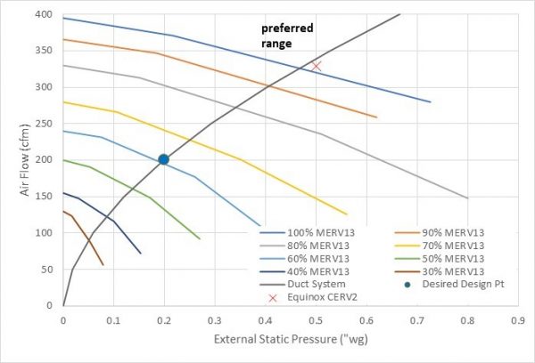
Figure 1 shows that a CERV2 with 60% fan speed can provide 200 cfm in a duct system with 0.2”wg pressure drop. A duct system that operates at 200 cfm and external static pressure of 0.2”wg, moves along the Duct System curve as CERV2 fan speeds are varied (see Figure 1). For example, increasing CERV2 fan speed to 90% for bathroom and kitchen exhaust events increases airflow to 300cfm with 0.4”wg of pressure drop. If the CERV2’s fan speed is reduced to 50%, air flow drops to 150 cfm with 0.16”wg.
In the world of ducts and pipes, things happen fast as diameter changes because of non-linear relations between pressure drop and air velocity. 10 feet of 4” diameter pipe with 200 cfm of airflow will have 0.2”wg of pressure drop, while 100 feet of 6” diameter duct has the same pressure drop for 200 cfm! As tempting as it is to try and squeeze a duct down in size, avoid the temptation! As discussed by Lovins, design ducts first, not last. Unfortunately, we see too many projects that leave duct design as an afterthought.
Field Measurements
External static pressure drop measurement allows you to check that the duct system designed has turned into reality. We installed a CERV2 in Equinox House last year, replacing the 10 year old gen 1 CERV. Built in 2010, Equinox House is a 2100 sqft, 4 bedroom home.
We re-designed Equinox House’s ductwork to accommodate the CERV2’s higher air flow capability. The inadequacies of ASHRAE’s odor-based ventilation standards became apparent as a growing list of research publications reported cognition impairment, sleep degradation, and elevated sick days at ASHRAE ventilation rates.
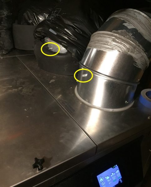
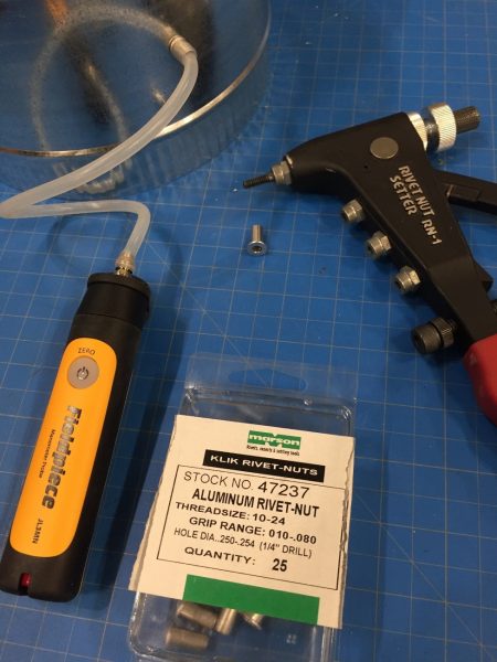
Figure 2 photo shows a convenient method for installing pressure taps in ductwork. We use ¼” rivet nuts in ducts connected to the CERV2. Plastic tubing conveniently slips over the rivet nut stem. The tubing can be connected to a handheld pressure meter, such as the Fieldpiece manometer (+/- 0.02”wg accuracy over a 2”wg range). The Fieldpiece manometer connects by Bluetooth to your phone so that you can move pressure transducers around a duct system while remotely reading output. Note: Build Equinox receives no compensation for cited products. There are several other good meters available with similar specifications.
A red ”X” on Figure 1 shows static pressure difference across supply and return ducts with 100% fan speed on the Equinox House CERV2. Our improved duct system more than doubled airflow of the original duct system at the same external static pressure. Among the duct improvements we made are:
- • Common supply duct to the master bedroom and main living area were separated into two separate 6” diameter ducts
- • An additional supply vent was added to the main living area, doubling the original vent opening area
- • A common 6” supply duct with 4” diameter branches supplying three smaller bedrooms was separated into three separate 6” diameter ducts
- • Primary return trunk was increased from 6” diameter to 8” diameter
Ten dampers were also added to the duct system for 5 return zones (3 bathrooms, laundry room and kitchen) and 5 supply zones (4 bedrooms and open living space). Future articles will discuss the CERV2’s advanced, plug-n-play zoning controls to maintain exceptional IAQ wherever you are in your home.
Fresh indoor air doesn’t just happen. Your household’s health depends on your ducts!
