Everything you need to know about how to install the CERV Indoor Air Quality Management system into a new home. New construction provides the most opportunities to customize the CERV to your home design, as you can optimize duct size and layout to the indoor air quality requirements. Additionally, new construction allows for proper insulation and sealing techniques to minimize heating and cooling loads in the house. In some cases, this provides opportunities to combine the CERV, ducted heat-pump, and dehumidifier into one single configuration, saving energy, complexity, and money!

Dedicated Ductwork
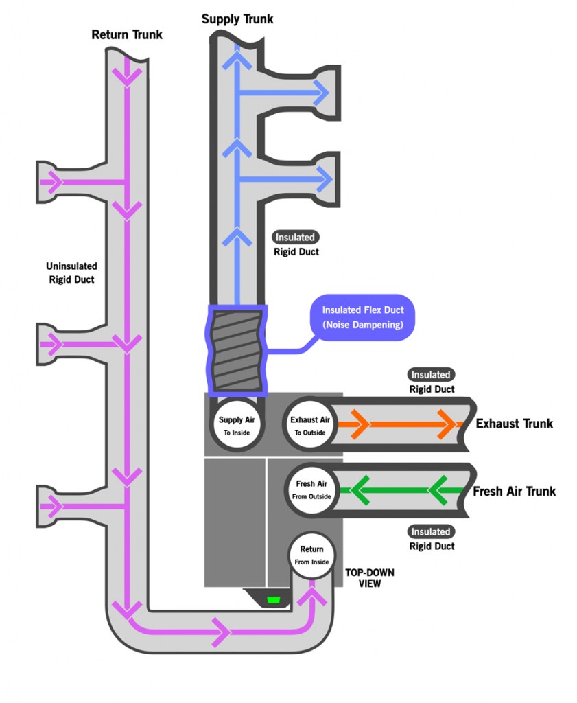
One configuration in a new construction home involves the utilization of dedicated ductwork tailored specifically for the CERV. In this setup, the system adeptly pulls stale air from high-pollutant areas like bathrooms and kitchens, effectively removing pollutants, moisture, and odors. Subsequently, it delivers freshly conditioned air to living spaces, ensuring optimal indoor air quality and comfort throughout the home. The main heating and cooling systems for the home could be radiant, ductless, or have their own separate ductwork.
Examples:
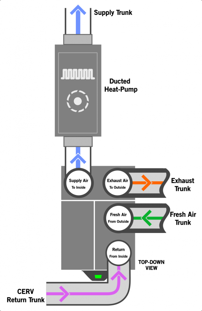
Magic-Box Concept: Ducted Heat-Pump in-line with CERV
If construction techniques for a new high-performance home are able to reduce the conditioning load enough, a ducted heat pump (typically 9000-12000btu) may be directly ducted in-line with the CERV to satisfy the entire home’s heating, cooling, and ventilation needs. In this scenario, the CERV can directly control the heat pump, intelligently managing house comfort as well as indoor air quality.
Tips and Considerations
- To control the Ducted Heat Pump, the CERV-IR-T Wireless Thermostat Controller Option may be used. The CERV-IR-T can interface with any system that has a traditional thermostat interface (R, G, W1, W2, Y1, Y2, G1, G2, G3) available.
Examples:
newspaperFeatured Article - Magic Box Mechanicals
newspaperFeatured Article - Taylor CERV2+Ducted Mini Install (2.5 Year Follow-up)
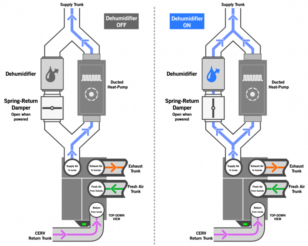
Magic-Box+ Concept: Ducted Heat-Pump and Dehumidifier in-line with CERV
If construction techniques for a new high-performance home are able to reduce the conditioning load enough, a ducted heat pump (typically 9000-12000btu) and dehumidifier may be directly ducted in-line with the CERV to satisfy the entire home’s heating, cooling, ventilation, and dehumidification needs. In this scenario, the CERV can directly control both the heat pump and dehumidifier, intelligently managing total house comfort as well as indoor air quality.
Tips and Considerations
- To control the Ducted Heat Pump, the CERV-IR-T Wireless Thermostat Controller Option may be used. The CERV-IR-T can interface with any system that has a traditional thermostat interface (R, G, W1, W2, Y1, Y2, G1, G2, G3) available.
- To control the dehumidifier with the CERV2, consider using the CERV2’s built-in dry-contact relay output (X0), the I/O Expansion Board Add-on (X1 – X6), or the Low Voltage Wireless Relay option.
- The spring-return damper will require a separate 24VAC transformer, and is generally controlled through the dehumidifier. More information on this can be found in the Dehumidifier Control Guide
Examples:
design_servicesDesign Resource - Supercharged Dehumidification with the CERV2
CERV2 With Forced Air System:
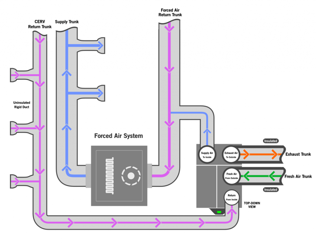
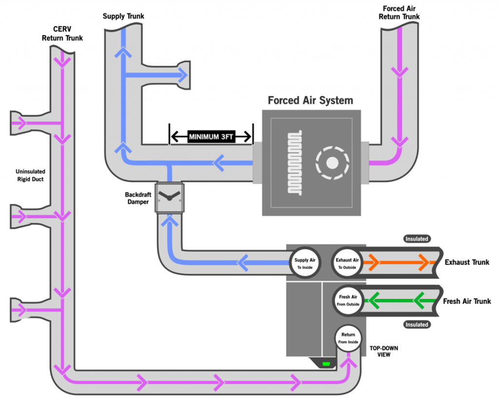
Dedicated CERV Return, CERV Supply to Forced Air System
The CERV2 seamlessly integrates with central air handlers, offering a seamless solution for homes equipped with larger HVAC systems requiring higher airflows. In one configuration, the CERV maintains its dedicated return ductwork for extracting air from bathrooms and kitchens while supplying fresh air to the central system. This integration can occur either on the return side, where the CERV feeds air directly into the central system, or on the supply side, utilizing a backdraft damper. This approach allows for the efficient distribution of fresh air throughout the home while reducing the cost of extra ductwork.
Tips and Considerations
- To interlock the Forced Air System to run when the CERV2 is running, consider the CERV2’s built-in dry-contact relay output (X0), the I/O Expansion Board Add-on (X1 – X6), or the Low Voltage Wireless Relay option. A powered backdraft damper may require the use of a second output.
- To interlock the CERV2 to run when the Forced Air System is running, consider the CERV2’s built-in dry-contact sensing input (I0), the I/O Expansion Board Add-on (I1-I3), or the Low Voltage Wireless Active Circuit Transmitter option.
Examples:
newspaperFeatured Article - CERV Retrofit: New Lungs for a 101-Year-Old Home
CERV Installation General Guidelines
Unit Installation & Ducting
- Avoid operating the CERV2 before construction has been completed, and ensure that ducts are covered to prevent drywall dust and other construction debris from getting into the ductwork.
- It is recommended to install the CERV2 in a plastic appliance basin if location is such that water damage is a concern. A clogged condensate line can cause water to pool around the CERV2. A moisture sensor and alarm can also be used to notify occupants of a problem.
- Fix the CERV into position and ensure stability. Unit must be level. Vibration pads can be placed under CERV to reduce vibration and to keep CERV off of a potentially wet floor surface.
- All ducts except for the Return (from inside) must be insulated. It is recommended to use a minimum of R4.0 insulation for supply to the inside and R8.0 on the ducts to and from the outside. In colder climates, it may be necessary to add additional insulation if it appears that the ducts may be showing signs of sweating.
Fresh Air Inlet & Exhaust Air Outlet Vents
- 8” diameter ductwork is recommended, 6” minimum.
- Exterior wall vents must be sufficiently above ground to avoid blockage from snow or other obstructions. Two feet above ground is recommended. Vents must use a coarse screen or mesh to prevent insects, birds, etc from entering, but fine screens and dampers, and flaps should be removed so as to eliminate any restrictions. Recommended wall vent: Mfr: Imperial, Part #: 6398901
- If possible both inlet and exhaust should be on same side of house to avoid pressure differential, which can impact flow.
- Inlet and exit ducts should be a minimum of 4’ apart in any orientation. Inlet separation from any other possible sources of contamination should be considered and local codes followed.
Bathrooms & Kitchen
- Bathroom vent fans can be used in-line with the ductwork to the CERV to boost airflow. Consider using the Active Circuit Transmitter option to trigger the CERV to vent while the fan is active.
- Do not duct a cooktop vent hood directly in-line with ductwork to the CERV. A recirculating vent hood may be used to remove grease and particulates from the air in combination with a CERV return vent in the kitchen. Any CERV kitchen return vent must be minimum 6ft from cooktop. Consider using the Active Circuit Transmitter option to trigger the CERV to vent when fan active.
Related Articles
newspaperSpotlight - CERV Retrofit: New Lungs for a 101-Year-Old Home
newspaperFeatured Article - CERV2 Retrofits in Metropolitan Milwaukee Homes
