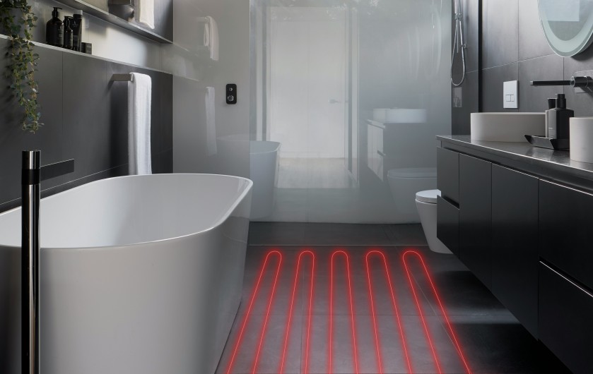
Radiant heating and cooling systems exchange heat between surfaces. An 86F (30 C) ceiling surrounded by walls, floor, and furnishings at ambient an ambient room temperature of 68F (20 C), transfers 80 to 100 Watts of radiant and convective heating per square meter of heated surface area.
The ”trick” to determining radiant heating and cooling rates is figuring out the radiant surface’s temperature. A tube with flowing fluid attached to the backside of a ceiling or floor surface doesn’t have a mechanism for keeping surface temperature constant. The fluid temperature continually decreases (heating) or increases (cooling) based on the length of the tube, flow rate of the tube, and composition and thickness of the floor or ceiling material.
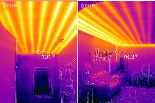
The pictures below show the ceiling of a 1950s era home with radiant ceiling heat. The system consisted of an old boiler (probably fuel oil initially, converted to natural gas) with a pump that distributed hot water to a complex series of steel tubing attached above the ceiling surface throughout the home. Infrared photos show the region heated by the tube is localized near the tube. High temperatures used in older systems (160 to 180F) used high temperature differences to drive heat into a room.
Today’s new generation of heat pump radiant heating and cooling systems operate with smaller temperature differences (105 to 120F for heating, and something cooler than room temperature but higher than dewpoint temperature for cooling). With smaller temperature differences driving heat transfer, more area is needed, but the good news is that there is plenty of surface area available for keeping a room comfortable.
An unfortunate consequence of today’s highly insulated and sealed homes with low heating capacity demand is that radiant floors will not “feel” warm. High performance homes rarely need floor temperatures above 80F to keep rooms comfortable, and relative to skin at 80F or higher, you will not feel a direct warming of your feet. Sadly, poorly insulated homes with high heating loads must use high temperatures to drive sufficient heat into a room for comfort. One might consider restricting the circuits used for radiant heating systems to a few select areas that are heated above 80F for a warm feeling. This might be regions in front of living room furniture, hallways or other places where feet are likely to land.
Brian Just (Efficiency Vermont) has an excellent presentation on renovation and installation of a radiant heating system, including a number of the decisions and challenges encountered. Any of John Siegenthaler’s web presentations on hydronics are excellent, too. This design guide by Zurn has a lot of practical information (note….we do not receive compensation for any products mentioned…..these are only examples).
Radiant Heat Transfer Model
It is difficult to find online sites with reliable information about radiant heating and cooling. Rules of thumb on floor ceiling surface area state 20 to 30Btu/h-ft2 as typical heat flow, but today’s transition from high temperature radiant systems (160 to 180F water temperature) to more efficient heat pump systems (105 to 120F) adds to the confusion as one is unsure if reference materials are based on older or newer operating conditions.
Growing interest in radiant cooling adds the difficulty of ensuring temperatures are kept above dewpoint everywhere in the tube loop and connecting surfaces. Hydronic circulation loops are decoupled from and unaware of a room’s humidity. A floor slightly below dewpoint quickly becomes wet and slippery while a ceiling that drops below dewpoint becomes a rain forest. An undetected, exposed tube surface in contact with higher dew point air will lead to mold and decay.
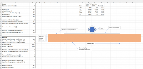
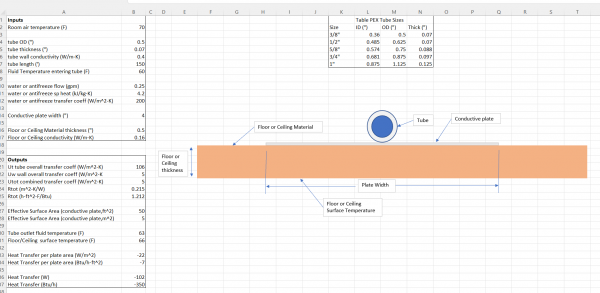
Build Equinox has developed an Excel spreadsheet model that determines heat transfer from a tube attached to a conductive plate that is fastened to a ceiling or floor. The active heat transfer area is the conductive plate. Tube length, tube diameter, fluid flow rate, fluid entering temperature and room temperature are primary spreadsheet inputs. Material properties and thickness are also input for the primary ceiling or floor material. The spreadsheet figure below assumes a fluid inlet temperature of 105F with water properties. Radiant systems with antifreeze would assume lower specific heat based on antifreeze concentration and properties.
A conductive heat transfer plate is important for spreading heat laterally from the tube circuit. Aluminum sheet metal is a good choice for the conductive plate. Here is one example. Aluminum’s high thermal conductivity allows it to efficiently spread heat across its width. The aluminum sheet from the online site is only 0.016” (0.4mm) thick, but thermally it is much more conductive than typical ceiling and floor materials.
Output from the model includes the overall transfer coefficient (“U-value”) and thermal resistance (“R-value”) from the tube fluid to the room for combined radiant and convective heat transfers. The tube outlet temperature, average surface temperature, and heat transfer rates are also predicted. The spreadsheet example shows 24Btu/h-ft2 (77W/m2) of heat transfer for a ceiling surface with ½” gypsum. The tube circuit is 150ft long, and a 4 inch wide conductive plate spreads heat from the tube to the ceiling surface.
Overall, the tube circuit is providing 1223Btu/h (357W) of heat with a surface area of 50ft2 (5m2). Outlet fluid temperature drops from 105F to 95F. The average radiant surface temperature is 85F. Depending on the room’s design day heating load, one can determine how many of these circuits are required to meet design day heating.
Try out our spreadsheet model. It’s purpose is to allow us to understand conditions needed for maintaining comfort with radiant systems as we work to understand the interrelation of household mechanical system impacts on our health and comfort.
Download the Radiant Calculator Spreadsheet Here
Radiant Cooling
Radiant cooling systems require careful examination to ensure all surfaces are above dewpoint temperature. Once a surface condenses a bit of water, it is more difficult to re-evaporate it, leading to extended wetness and a long list of problems.
Warming air from 50F and 100% relative humidity to 70F results in 50% relative humidity. Any surface in the room at 50F will locally cool adjacent air to 50F and 100%rh, the air’s “saturation” (dewpoint) condition. Further cooling below dewpoint will cause condensation on the surface, as we see whenever we remove something from a refrigerator.
Radiant cooling requires both air conditioning and radiant surface temperature analyses. Adjustments must be made to the air’s conditioning (, dehumidification) and/or the radiant cooling system’s operation (increased fluid temperature). Build Equinox’s free-to-use, online house modeling ZEROs (Zero Energy Residence Optimization software) coupled with our Excel radiant surface design tool will let you conduct both analyses in a straightforward manner.
Part 4 of our “Handling Humidity” report series shows results from ZEROs for three different contractors, Contractors “Loose”, “Tight”, and “Smart”. Contractor Loose builds a house with 6ACH50 infiltration while Contractors Tight and Smart build a home with 0.6ACH50 infiltration. The difference between Contractors Tight and Smart is that Tight ventilates through a high efficiency ERV at ASHRAE 62.2 conditions while Smart ventilates in a smart manner with a CERV2 that maintains higher air quality than ASHRAE 62.2 but uses less energy. Read how to install whole house dehumidification controlled by the CERV in our article: CERV2 Smart, Integrated, Supercharged Dehumidification.
Example cases in Handling Humidity (Part 4) show that a home in Phoenix requires less than 20 liters per day of dehumidification capacity in all three cases because Phoenix’s dry air minimizes moisture problems (but doesn’t eliminate them). Contractor Loose in Miami requires 85 liters per day of dehumidification, followed by Tight’s constant ventilation that needs 50 liters per day while Contractor Smart’s home only needs 25 liters per day of dehumidification to maintain indoor conditions of 74F and 60% relative humidity.
A room with 74F and 60% relative humidity ambient conditions has a dewpoint of 60F. Any surface below 60F will have condensation. Reducing room air humidity to 50% reduces the dewpoint to 50F, increases radiant surface cooling capacity, however this level of humidity requires significantly more dehumidification energy in regions with high outdoor humidity.
Using the Excel spreadsheet model, and assuming inlet water at 60F for the tube circuit parameters used in the previous heating example results in 102W of radiant cooling for the 150ft long cooling circuit. If the required number of tube circuits fit in the room’s available area will meet room’s sensible cooling requirement, one can be reasonably assured that no moisture problems will occur. The average radiant surface temperature is 66F and the tube fluid’s outlet temperature is 63F.
If the cooling capacity of the above example needs to be increased and there is no room to add additional cooling circuits, colder fluid must be supplied to the tubes. From the Excel model, 50F inlet fluid increases the tube circuit cooling capacity to 204W. Dewpoint in the room air must be lowered below 50F (that is, 50% relative humidity at room temperature) in order to avoid condensation. ZEROs will provide information on required dehumidification capacity.
Download the Radiant Calculator Spreadsheet Here
Radiant without Hydronics
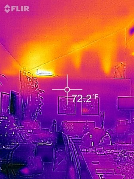
Radiant heating and cooling is not restricted to hydronic systems! The picture below shows how we use a 1 ton ductless minisplit heat pump to heat and cool the ceiling in Equinox House’s open living space. Heated (winter) or cooled (summer) air moves along the ceiling through most of the room before turbulent mixing with room air. The ceiling surface efficiently transfers comfort to room occupants. Note the two vertical plumes from the CERV unit delivering heated, fresh air to the room as well.
Summary
Radiant comfort conditioning is growing. How far it grows in North America is to be determined. An advantage to radiant systems is a reduction in air flow through a house to a level needed for maintaining a healthy indoor environment.
Radiant systems are not being installed at the exclusion of air source heat pumps, in fact, we see several projects integrate and unify the operation of ducted minisplit heat pumps and ducted dehumidifiers into their CERV2’s operation. This combination provides nimble management of house comfort conditions in harmony with a radiant system while also providing a level of redundancy if one system fails.
Related
linkPresentation: Renovation and Installation of a Radiant Heating System
linkZurn: Radiant heating Design and Application Guide
linkBuild Equinox Radiant Flooring Calculator
design_servicesDesign Resources - Handling Humidity: Understanding and Modeling Humidity
design_servicesDesign Resources - Supercharged Dehumidification with the CERV2

